Logitech G27 pedals are well constructed, but the pedal feel and the brake response leave a lot to be desired. The lack of a pressure based brake made it difficult to consistently apply the same amount of braking. The first upgrade I installed was a GTEye progressive spring, which made the brake firmer, and a bit more progressive feeling. I think it would actually be better if it was more progressive, it still didn’t feel realistic. Keep in mind that firmer pedals require a more sturdy rig to mount your setup on.
I figured the braking accuracy would be better with a load cell. A potentiometer has limited resolution at the point when the brake gets progressively firmer, because the potentiometer reads movement rather than pressure. So I looked at the load cell options available for the G27/G25. The APElectrix mod uses a button load cell, which sits inside the red spring housing and limits spring length and pedal travel, which didn’t seem ideal. You could buy your own button load cell, and work out a spring combination that you like. I had seen a load cell mod for T500 pedals that used a beam load cell and looked more durable. I set out to make something similar for the G27.

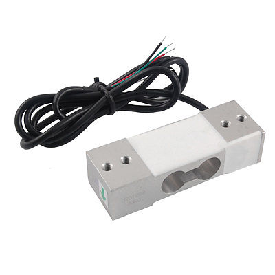
I didn’t want to cut my logitech pedals into pieces, and I wanted to keep the plastic cover on them to protect the wiring and potentiometers. I ended up going for a 30kg beam style load cell, which was wide enough to have good support on the standard G27 pedal arm. Here’s the load cell I used from eBay. It costs a whole $30. The wiring colors were different to the picture, the red wire was 5v in and the yellow was ground. If your load cell isn’t working, here is a useful troubleshooting guide for load cells, which shows how to measure resistance to work out the wiring.
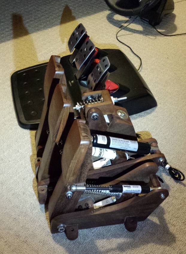
I mounted it onto the brake pedal arm using some rectangular washers (from road bicycle pedals), which I ground to the right shape. It’s important that the load beam is only supported at each end, and free to bend in the middle. I made up some timber pedals for all three, in order to make them the same length and a comfortable angle. The longer pedals have a better feel than the original shorty setup. I made the accelerator pedal angled so that it was a bit more upright. 
The load cell needs to be amplified by a load cell amplifier circuit, which you can buy premade from Leo Bodnar here. I wouldn’t recommend the effort of building one yourself on proto board, like I did. However, if you really want to build the load cell amp, here’s an example circuit, with a INA122 instrumentation amplifier. This particular load cell I’m using will output 0.7mV/V at its rated maximum force, which gives 3.5mV output with a 5V supply. Most load cells output 0.2mV/V. According to the INA122 datasheet, a gain resistor of about 400 ohms will produce a gain of 500 (I used a 500 ohm mini trimpot, so I can adjust the gain). I think the Leo Bodnar load cell amp uses approximately a 420 ohm gain resistor.
The load cell amp connects to the three leads that were originally on the brake potentiometer. The brake output on my load cell amplifier is the inverse direction of the normal Logitech pedal axis, so your racing games will need to be setup accordingly. I have only used this mod on Windows, I don’t imagine it would work on console if the axis is reversed. DXTweak is a utility which lets you adjust dead zones, etc for controllers. It’s worth grabbing, so you can see the raw input from the pedals. If your signal is noisy in DiView / DXTweak, then make sure you have a filtering capacitor across the voltage input pins, and that the capacitor polarity is correct in your circuit. Update: I did some troubleshooting and made some improvements to my DIY INA122 load cell amplifier circuit.
In order to make the brake pedal more progressive feeling, I cut a 35mm-40mm long piece of garden hose, and put it inside the GTEye progressive spring. The garden hose means that the pedal resistance is provided by the progressive GTEYE spring for the first part of the travel, and then the resistance ramps up steeply in a similar way to brake pads pressing onto a rotor. Because the load cell is external, you have the full length of the red spring housing to work with in terms of braking feel, to suit your preferences.
You could get creative with a combination of spring, hose and dense foam for example. I put the original brake pedal spring in the clutch, and the clutch spring in the gas pedal. This works ok with the extra leverage that the longer wooden pedals provide. When changing pedal length, keep in mind that doubling the leverage ratio actually requires 4x the spring rate in order to feel the same at the foot. This is because the pedal will have twice the leverage on the spring, but in addition the spring only moves half the distance (and spring rate increases linearly with compression distance). This means the long pedal arms will feel very soft if you only have a gteye spring in there.
The upgrade to pressure based braking makes a big difference to realism, I like how it feels. You might think that wooden pedals don’t seem quite right for a real car, but your driving sims with bare feet they are much warmer and more comfortable than aluminium pedals.
Update: Now that I’m using a phenomenal OSW direct drive wheel, I decided to build some high end brakes from scratch, that are easier to modulate. I really can’t praise the OSW wheel enough, it’s a whole new level of realism. I wanted even longer pedal arms, and a more progressive, firmer brake. The Heusinkveld pedals seem to be the best pedals you can buy, with brilliant customer service, but they’re a bit too pricey for me. I figured I could build a complete pedal set from wood, so that’s what did. I purchased some bearings, some more beam load cells, coil springs, urethane springs, PTFE tubing, bolts, nuts and threaded rod. I added hydraulic dampers on all three pedals for added control, just like the Heusinkveld Ultimates. Here is the build log for the new pedals. They offer fabulous braking control, and a supportive throttle that allows for smooth application.
Having built the new pedals, I had another thought on making the g27 mod more progressive. I suspect you could probably use a pair of coins and a rod of urethane which fits within the coil spring to provide a firm and progressive second stage. You would want a bit of travel before the urethane engages, for a dual stage feel. Good luck, and happy racing!

This is exactly what I’ve been looking for! I’m assuming this will also work for a G25?
LikeLike
Yes, you’ll be able to do a similar mod to the g25. I think that changing the spring and making it very progressive is important for braking consistency (such as a spring and elastomer combination).
LikeLike
Yeah thats what I like. Long ago I bought a elastomer insert mod (and have extended pedals and have hung them upside down) but it’s been so long I can’t remember what it was. But thats what I like about your system is that I can use the cylinder just to fine tune force/progressiveness/feel in almost any way which the plastic parts are well suited for. With whats offered at McMasterCarr.com the possibilities are almost endless. I’ve also been intrigued about using elastomers that are sub cylinder size but at some point reach the cylinder ID and instantly get even more progressive. Although the cylinder may require some sort of clamp to prevent splitting but that would be easy. I’m a mech engineer and having used load cells for experiments (set up by others) I was just having problems paying the price for some of the retail mods but they are good proven and offer ease of use. So I was thrilled to find this site. I can’t believe this site isn’t blowing up on iRacing forums.
LikeLike
Same 100K pot right? I also have the Leo Bodnar USB cable.
LikeLike
Actually not “more progressive” but really a highly progressive almost hydraulic solid lockup that can be almost infinitely fine tuned in length and forces using elastomers (one or multiple pcs) that vary in durometer, length, OD (and even ID), spacers etc. Thats a perfect use for those old G25/27 parts! Genius.
LikeLike
Nevermind. I should have just read through it again. I just ordered everything I need for about $40US! You are awesome!
LikeLike
Hi,
I have read your blog and you have inspired me to also make some changes to the standard G27 wheel and pedals. I want to change the brake pedal to a load cell type and have a question before I rush off buying parts. Could you please help?
The standard G27 pedals work with voltage signals 5V to 0V (fully pressed pedal) but a load cell with the amplifier will give a signal 0V to 5V (fully pressed pedal). I have searched everywhere but cannot find how to invert the axis so the pedal works correctly. What is the trick here, does the logitech software work this out on its own? (Windows 10, Project CARS)
I have experimented with DXTweak and found that the logitech software calibrates the pedals constantly in the background if a raw value greater than what is stored is seen then the new value is used as the max and likewise for the minimum. I have tried to replicate the load cell signal by powering the G27 up with the pedal fully pressed (0V) and during calibration releasing it (5V) and pressing fully again but this does not work. The logitech software still expects a 5V to 0V signal. DXTWeak doesn’t have any functionality that would allow me to invert the axis either. What am I missing?
Thank you for your help in advance.
LikeLike
I think it just works it out. Try reversing the direction of wires going into your existing pedal brake potentiometer and you’ll be able to test it for yourself.
LikeLike
Thank you
LikeLike
I just got mine to work. albeit signal is reversed, Assetto Corsa is able to recognise it correctly and I’m able to brake correctly. Just click the Brake in your controller setting if your are in AC, then press the new load cell, AC will be able to recognise it correctly.
Also, this amplifier by chippedwood, my USB doesn’t like it, it would disconnect the board/G27 whenever i connect the 5V to the amplifier, if i supply 5V to the amplifier from external source, and just pull the signal, it’s fine.
Then i found the below link, mod for T500R, much simpler, and didn’t have problem with my USB.
http://cbtechnical.blogspot.my/2011/04/amplifier-circuit.html
Took me loooooooong time to figure out
LikeLike